Cal Aero SAE Wing
Wing Design Engineer · Cal Aero SAE · UC Berkeley · Sep 2023 – Apr 2024
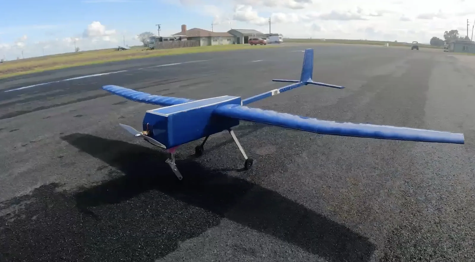
I worked out the final shape of the wing for our competition plane, sized its spar, and helped build it. The plane flew and placed top 15 in the Regular Class at SAE Aero Design West 2024.
Top 15
Regular Class, SAE Aero Design West 2024
10%
less spar material, with strength and stiffness targets still met
15 ft
wingspan of the plane the wing was built for
7.25°
dihedral on the wing tip sections in the final design
What I did
- Ran airfoil and dihedral simulations in XFLR5 and MATLAB to set the wing geometry, including how much the wing tips angle up and where.
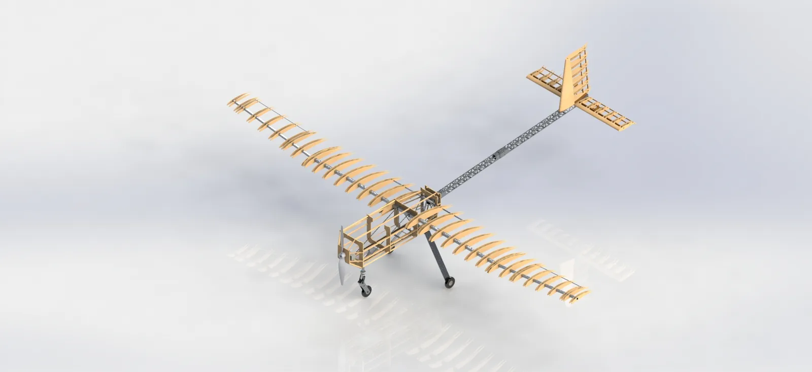
- Designed the wing structure in CAD.
- Sized the wing spar in MATLAB by working out shear, bending moment, stress, and deflection along the span, and took 10% out of the material while still meeting strength and stiffness targets.
- Laser-cut the airfoil ribs and built the balsa wing.
- Learned manufacturing from scratch on the team: the laser cutter, cutting airfoils, and assembling a wing that matched the CAD.
The hard part
The dihedral simulations were complicated and confusing at first. I also had to learn manufacturing from scratch: the laser cutter, cutting airfoils, and building the wing.
How it turned out
The wing we built matched the design, the plane flew, and we placed top 15 in the Regular Class at SAE Aero Design West 2024.
Flight test
Flight testing the plane.
Engineering detail
The full story for anyone who wants to dig in: design decisions, numbers, and what didn't work.
The challenge
SAE Aero Design West scores teams on how much payload their plane can carry, and the plane has to take off in a 100 ft runway. Everything is a trade: a bigger wing lifts more but weighs more, and a wing that is too weak fails in the air. In the previous season, our plane did not have enough thrust to take off safely, and it did not survive the resulting crash. This year's goal was to fly, first and foremost.
The plane we designed has a 15 ft wingspan, a 35 lb maximum takeoff weight, and is built to carry up to 12 lbf of payload. My job was the wing: its shape and its structure.
Wing geometry
The team chose the DAE-31 airfoil. Several airfoils had similar lift-to-drag ratios, but the DAE-31 was the one we could actually build, since our balsa construction can't handle the very thin trailing edges of the alternatives. The wing also has a washout (twist) from 4.5° at the root to 0° at the tip and a slight forward sweep, both to improve stability and performance.
My part was the simulation work to settle the wing's final shape in XFLR5 and MATLAB, including the dihedral.
Dihedral study
Dihedral is the upward angle of the wing tips. Too little and the plane won't recover from a roll. Too much and you lose lift. Early simulations showed our plane's spiral mode was too fast: the time for the spiral to double in size was only 2.6 seconds, which is hard for a pilot to catch.
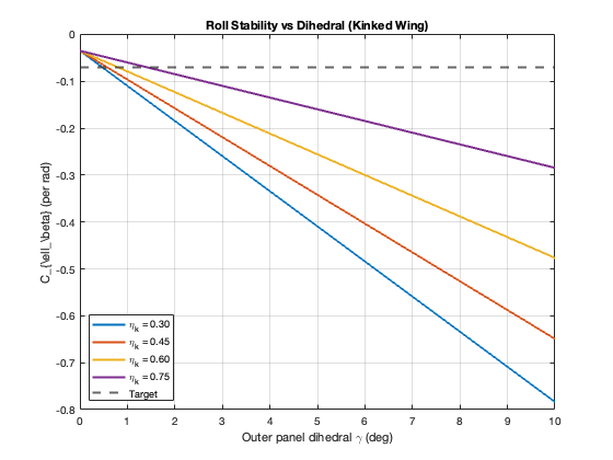
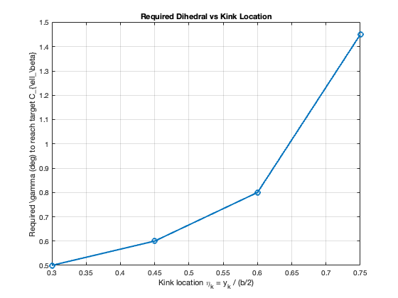
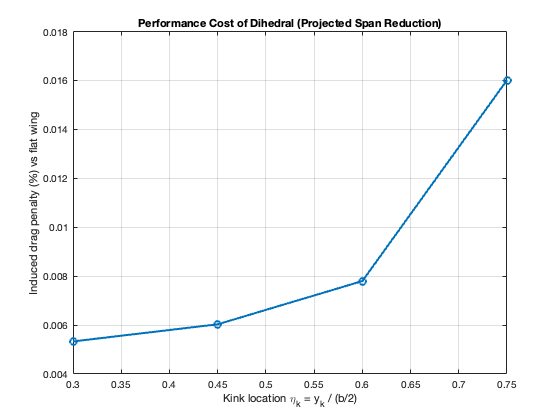
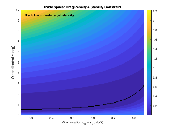
The required effective dihedral came out to about 12.25°. A high-mounted wing supplies roughly 5° of that on its own, so the wing itself needed about 7.25° of dihedral. Because of the competition's modularity rule, we got the dihedral by mounting the tip sections at an angle to the root sections. That keeps the root, where lift matters most, flat. With these changes the spiral mode's time to double went from 2.6 s to 5.8 s.
These plots map the trade space: the stability I needed against the drag that dihedral costs, as a function of where the wing tip section starts.
Spar sizing
The spar is the beam inside the wing that carries the lift. A spar that is too light fails, and one that is too heavy costs payload, so the goal was the smallest spar that still meets the requirement.
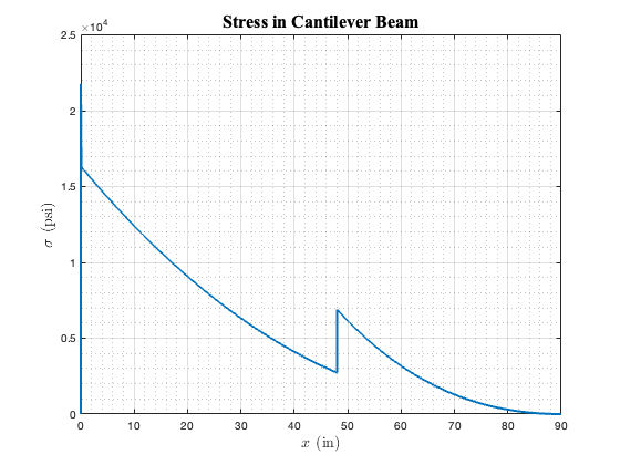
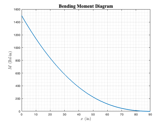
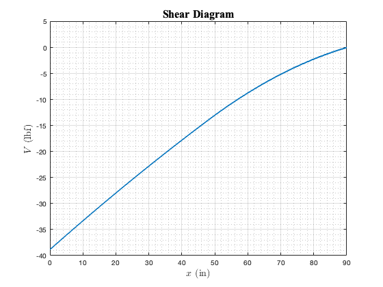
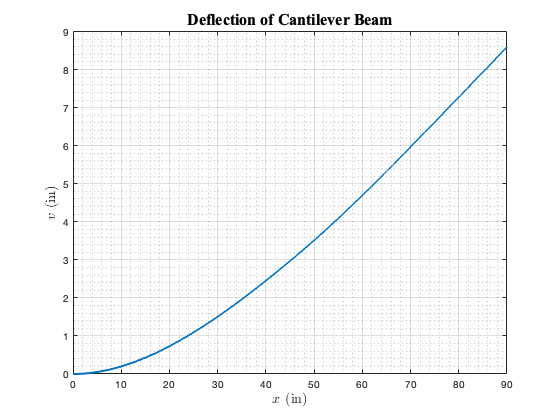
I treated the spar as a beam under the real lift distribution on the wing. In MATLAB I integrated that load to get shear force and bending moment along the span, then computed stress (σ = Mc/I) and deflection from the spar's cross-section. The spars are telescoping tubes, so the second moment of area steps down along the span, and the script accounts for that. I checked the strongest and weakest points against our targets and trimmed material wherever there was margin, which is where the 10% savings came from.
The team's finite element analysis of the wing spar peaked at about 19 ksi, and the design carries a minimum safety factor of 2.4 over normal operation.
Building the wing
The wings use a hollowfoil construction: two thin laser-cut balsa airfoil profiles joined by an outer skin, which resists buckling and bending at very low weight. The team load-tested hollowfoils at three rib thicknesses. All carried the test load, but the thinnest were inconsistent to glue, so the center sections use 1/8 in ribs and the tip sections use 3/32 in ribs. The spars inside are aluminum 6061-T6.
I laser-cut the airfoil ribs and built the wing.
Final design