MotoStudent Race Motorcycle
Rear Suspension Lead · UC Berkeley · Sep 2024 – Dec 2025
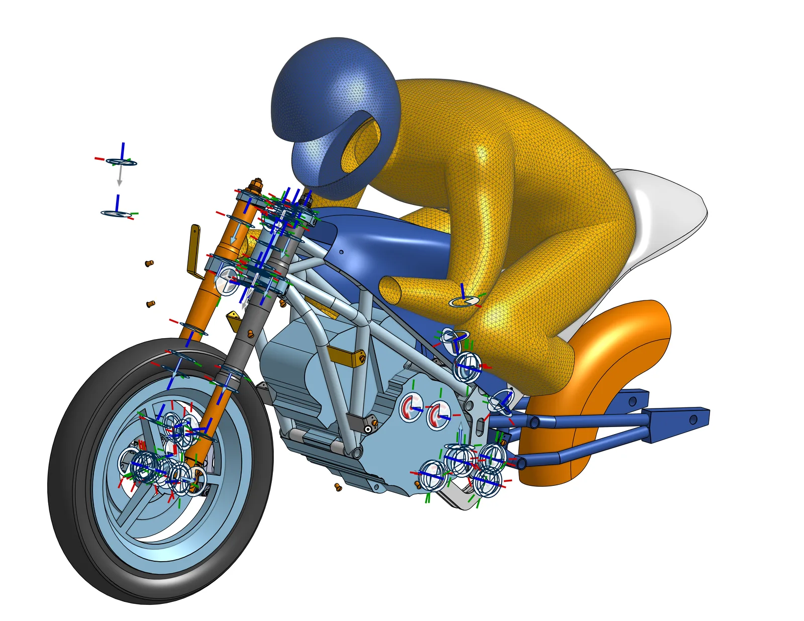
I led the 5-person team that designed the back half of a race motorcycle: the swing arm, shock, and linkage that keep the rear wheel planted on the track.
5
engineers on the rear-suspension subteam I led
100s
of linkage iterations before the geometry was final
~97 mm
of designed rear wheel travel
~2×
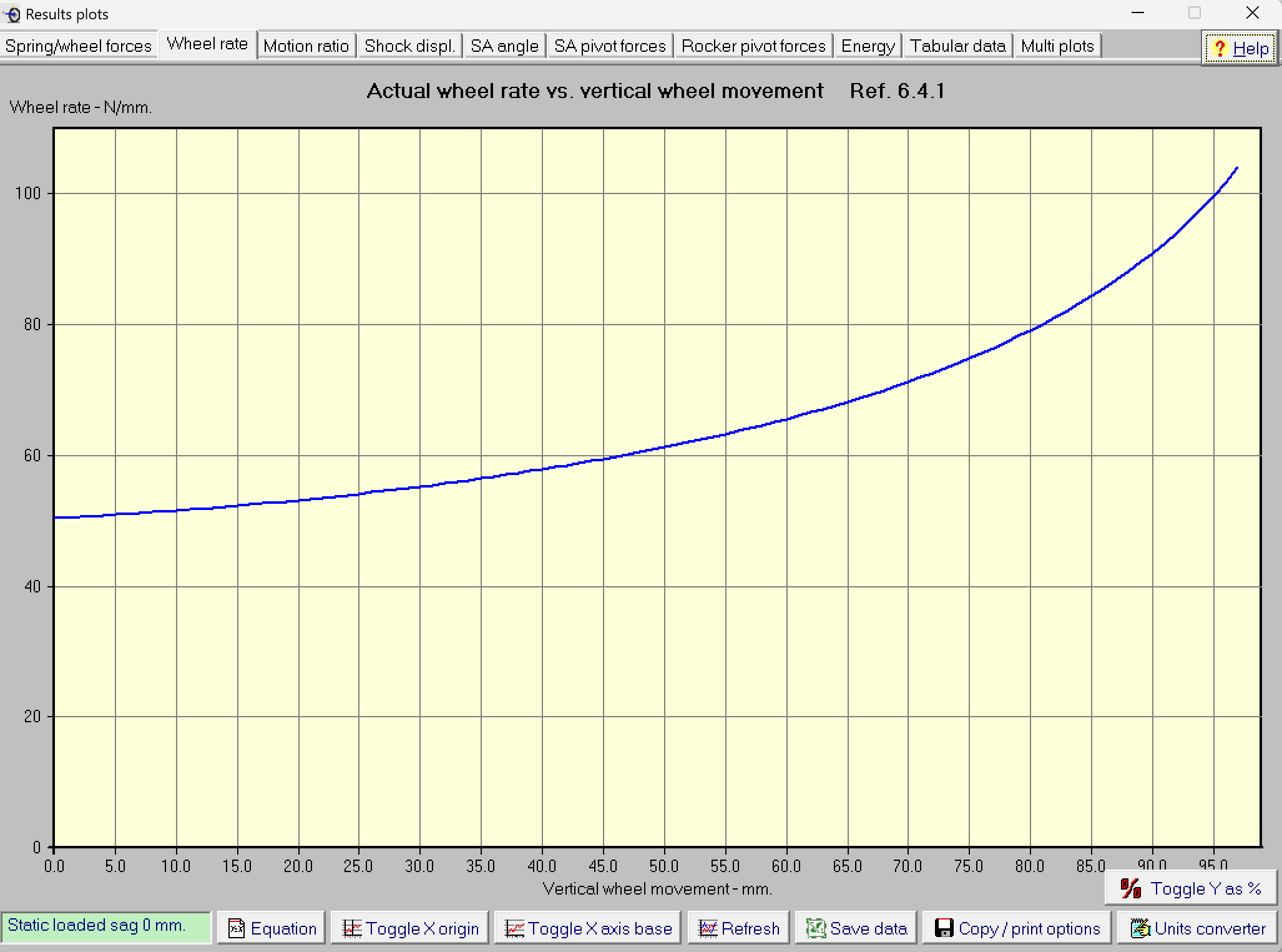
rise in wheel rate across that travel, concentrated at the end
What I did
- Led a 5-person subteam designing the rear suspension for the MotoStudent international competition in Spain.
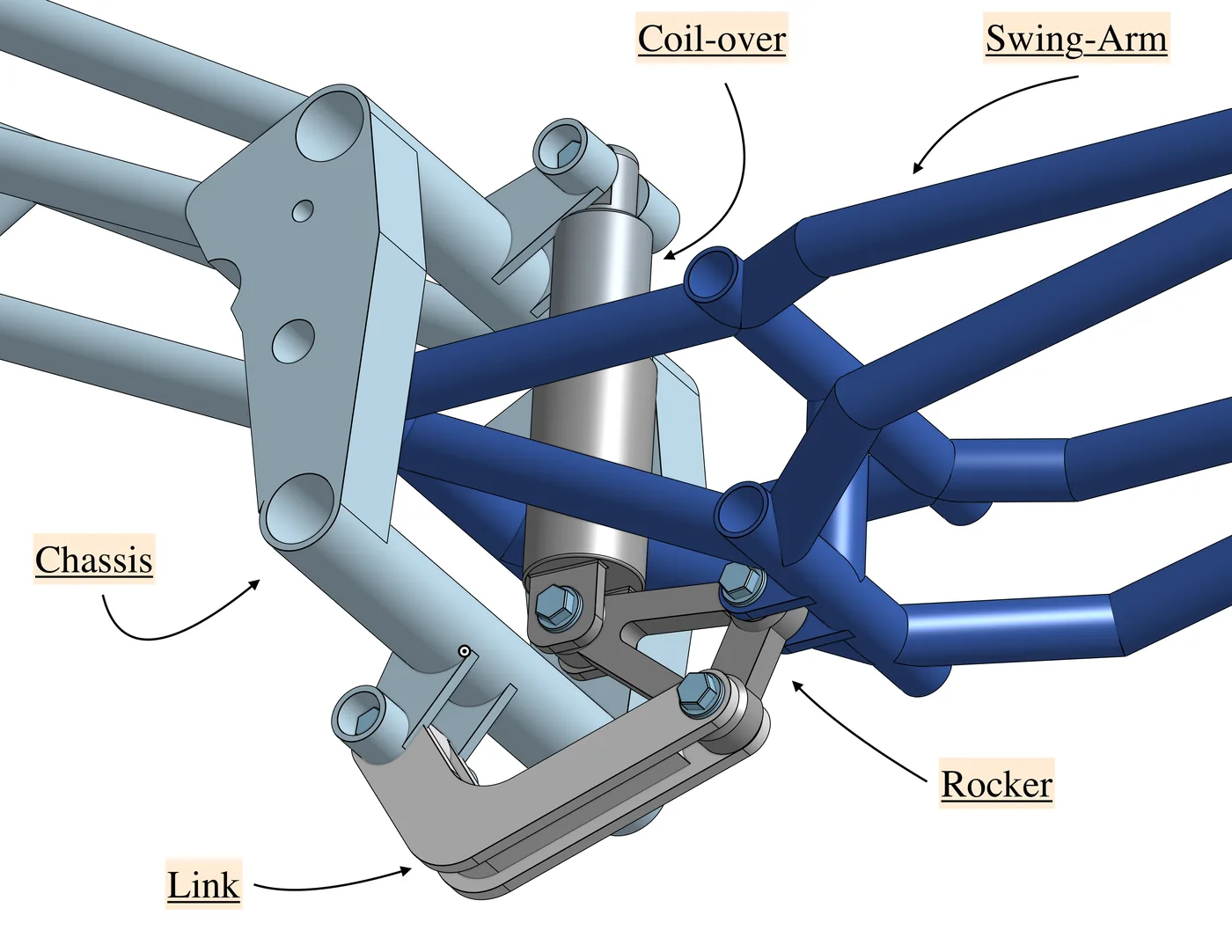
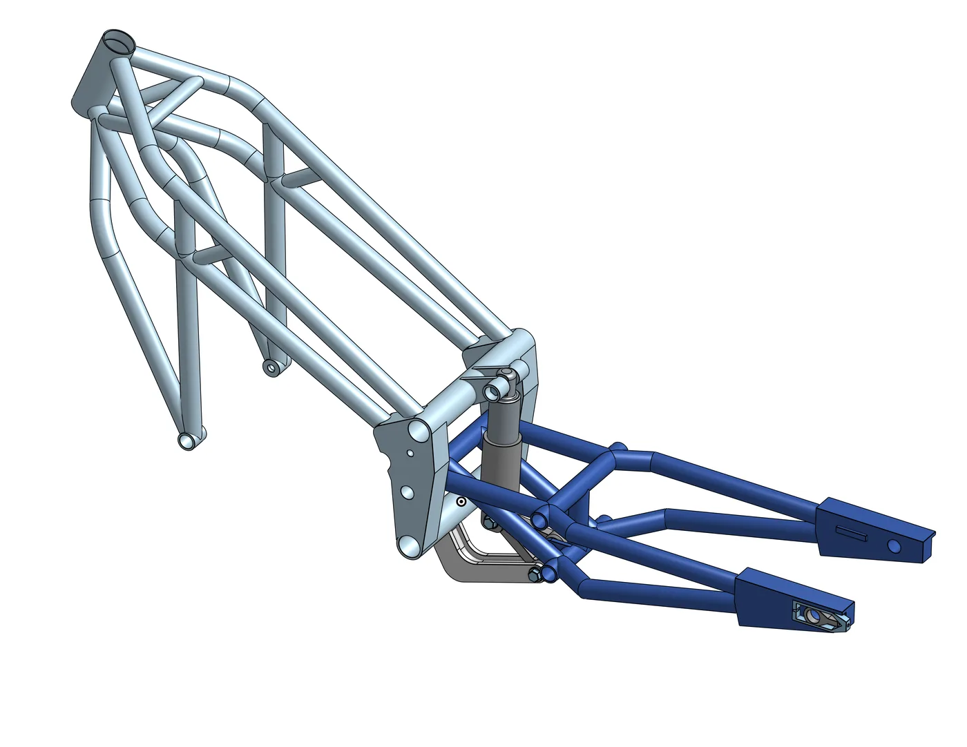
- Owned the whole rear end: coil-over shock, swing arm, rocker, and linkage, plus how it all mounts to the chassis.
- Went through hundreds of design iterations in MotoChassis to find a geometry that matched the suspension behavior we anticipated: close to linear through most of the travel, then stiff as a board in the last bit where the forces are highest.
- Compared solid-body and trellis swing arm designs in Onshape.
- Worked out packaging, mounting points, and clearances with the chassis team so the rear end fit the frame.
- Did the full CAD for the rear end and released it to manufacturing.
- Rebuilt the subteam with committed people after the first group fell through, and started writing everything down.
The hard part
My first subteam wasn't committed, and there was no documentation from earlier years. I carried a lot of the work myself until I rebuilt the team. Now I set expectations and write things down from day one.
How it turned out
The geometry and dimensions I set were carried into the design that went to manufacturing. The full bike wasn't finished before I graduated.
Rear suspension CAD
Engineering detail
The full story for anyone who wants to dig in: design decisions, numbers, and what didn't work.
What the suspension has to do
A race bike's rear suspension has two jobs that pull against each other. Through most of its travel it should be soft and predictable, so the tire keeps contact with the track over bumps and under hard braking and acceleration. At the very end of the travel, where the load is highest, it has to firm up fast so the bike doesn't slam into its limit.
Our anticipated suspension did exactly that: close to linear through most of the stroke, then very stiff in the last bit of travel where the force is largest. My job was to find a linkage geometry that delivered that behavior while still fitting inside the frame.
Hundreds of iterations
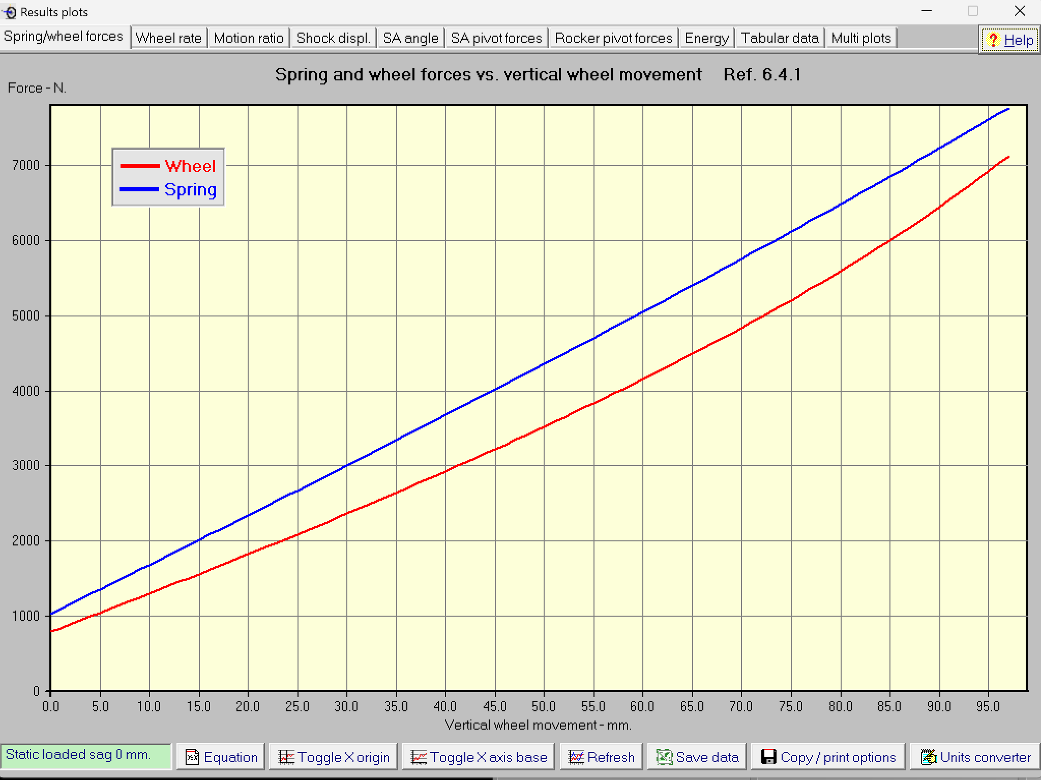
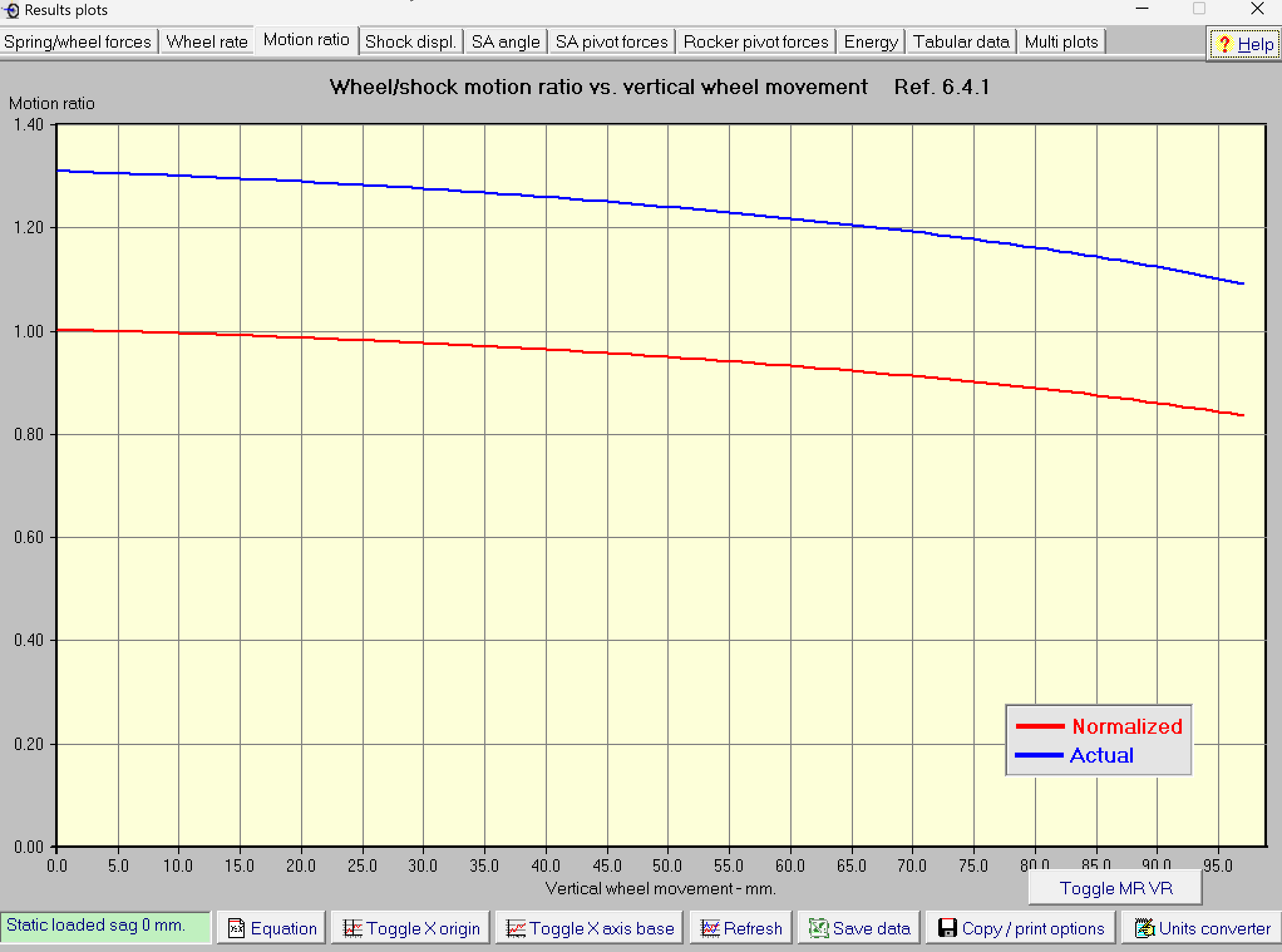
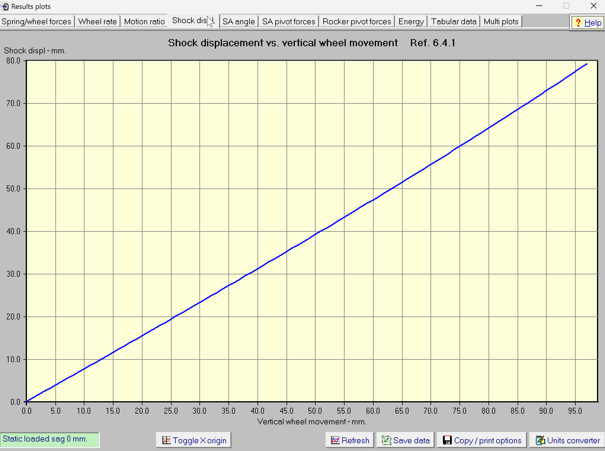
In MotoChassis I varied the linkage geometry (pivot locations, rocker and link lengths, shock mounting points), then re-ran the kinematics and checked four plots against our targets: spring and wheel force, wheel rate, motion ratio, and shock displacement.
Nothing in a linkage can be changed on its own. Moving one pivot shifts the motion ratio, which changes the wheel rate (wheel rate scales with the motion ratio squared), which changes how much shock stroke you need, which changes whether the shock still fits the packaging. That is why it took hundreds of passes instead of a handful: each one had to improve the curve without breaking the geometry or hitting the chassis.
The final design was then locked into CAD with the chassis mounts and clearances worked out, and handed to manufacturing.
Final geometry, by the numbers
| Quantity | Final design |
|---|---|
| Rear wheel travel | about 97 mm |
| Shock stroke over that travel | about 79 mm, nearly linear with wheel motion |
| Motion ratio (wheel : shock) | about 1.31 at full extension, easing to about 1.09 at full compression |
| Wheel rate | about 50 N/mm at the start, 60 to 65 N/mm through the middle, rising to about 104 N/mm at full travel |
| Spring force | about 1,000 N at the start to about 7,750 N at full travel |
| Force at the wheel | about 800 N at the start to about 7,100 N at full travel |
Values read from the MotoChassis plots below.
Kinematics (MotoChassis)
These plots are the result of that iteration. The wheel rate plot is the one I cared about most: it stays gentle through most of the travel, then climbs steeply at the end. That is the stiff-at-the-end behavior we wanted.
Swing arm and packaging
- Compared solid-body and trellis swing arm designs in Onshape before committing to one.
- Worked out the mounting points and clearances with the chassis team so the rear end fit the frame.
- Carried the final geometry into the full rear-end CAD and released it to manufacturing.
What I took from it
The hard problems on this bike were at the handoffs between subsystems: where the swing arm meets the chassis, where the linkage meets the shock. With no documentation from earlier years, I learned to set expectations with the team on day one and write things down from the start.