Wind Turbine Design and Testing
Team of 6 · E26 with Professor Ken Youssefi · UC Berkeley · Fall 2023
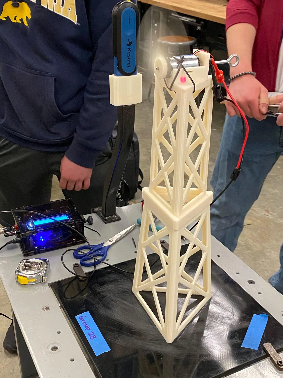
We designed a small wind turbine to be stiff, light, and make as much power as possible, then 3D-printed it and tested it.
1.56 W
peak power in a 25 mph wind
~262 g
total weight of the printed tower
0.53 mm
tower deflection under a 1 kg load
~18.5 N/mm
measured tower stiffness
What I did
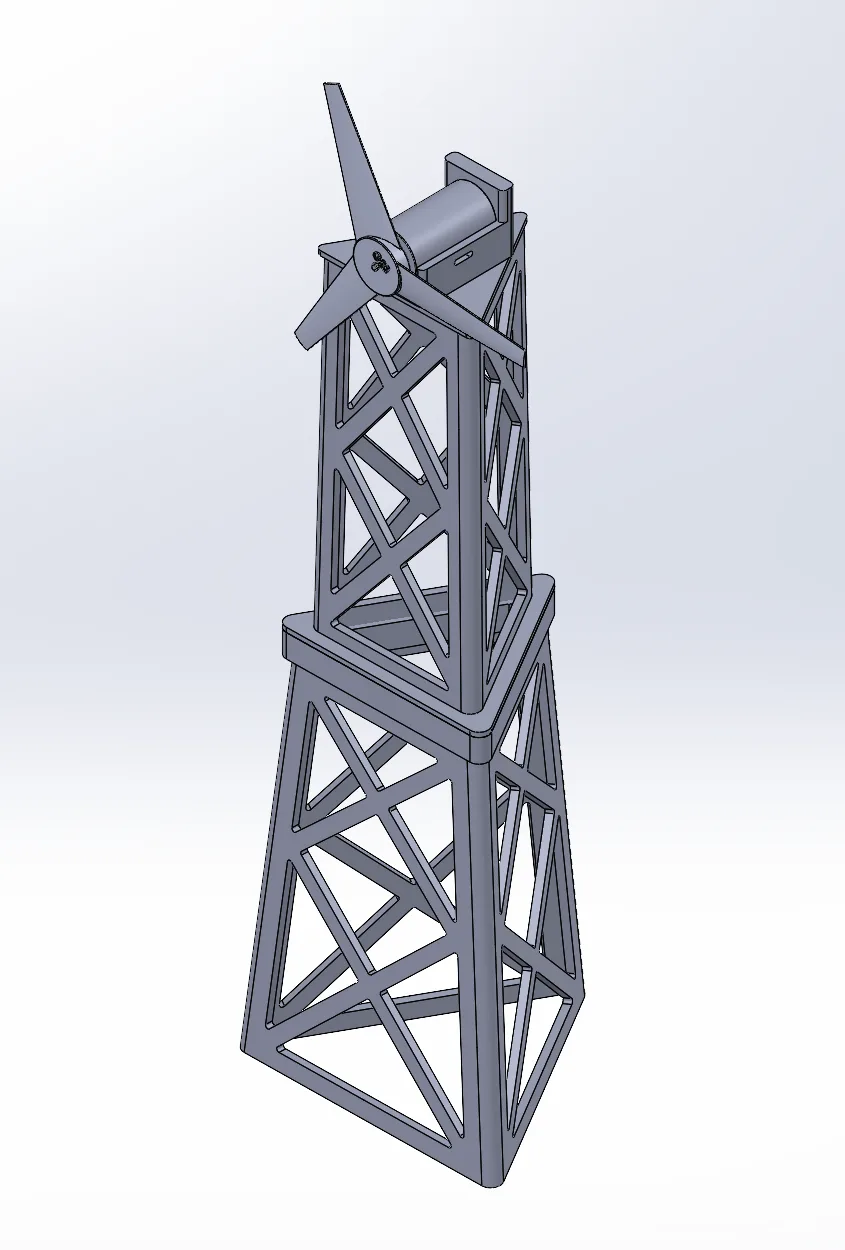
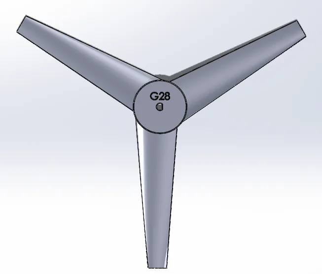
- Worked on the rotor blade design: three blades, SG6043 airfoil, 13° angle of attack and 12° twist, tuned for a 25 mph wind.
- Worked on the tower: a triangular, cross-braced truss designed for the most stiffness per gram within a fixed volume.
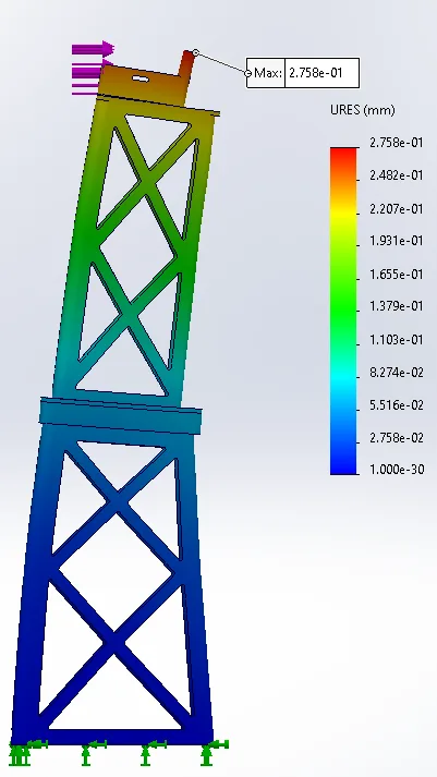
- Modeled the parts in SolidWorks and ran FEA on the tower to predict how much it bends under load.
- Helped test power output at a controlled wind speed with a tachometer and a variable electrical load.
- Helped measure the tower's stiffness by hanging weights from it and recording deflection.
How it turned out
The turbine made a peak of 1.56 W at 25 mph, and the tower held a 1 kg load with just 0.53 mm of deflection.
Design and analysis
Engineering detail
The full story for anyone who wants to dig in: design decisions, numbers, and what didn't work.
The assignment
Design a wind turbine rotor and tower that maximize stiffness and power output while keeping weight and volume low. The generator, gearbox, and brake were out of scope, so the work was entirely in the blades and the structure that holds them.
Rotor blade
| Parameter | Choice | Why |
|---|---|---|
| Number of blades | 3 | More blades add little beyond three, and fewer blades keep weight and drag down |
| Airfoil | SG6043 | Picked from published small-turbine airfoil comparisons for power output |
| Angle of attack | 13° | Research pointed to 10 to 15°; chosen to maximize lift at the design wind speed |
| Twist | 12° | Keeps the angle of attack effective along the blade; research supports about 12° for a 23 mph wind |
| Design wind | 25 mph | Matched to the test setup |
| Material | 3D-printed ABS | Fast to iterate; blades are light and lightly stressed |
One limitation: the 3D printer couldn't produce the very thin edges of the airfoil, so the blade ends had to be filleted. That changes the airfoil shape slightly, and it's the first thing I'd revisit by picking an airfoil that prints cleanly.
Tower
The tower is designed only for stiffness. Its shape borrows from an electrical transmission tower: an equilateral-triangle base for rigidity, with crossing trusses instead of solid walls. The trusses cut the volume compared with solid infill while keeping the structure stiff. It is 16.5 in tall with a 4.8 in base and a total volume of 16.83 in³.
The tower is too big for the printer in one piece, so it is split in two with slots that align the halves before gluing.
FEA versus the real thing
I applied a 1 kg force normal to the back of the motor housing at the top of the tower, with the base fixed. The simulation predicted a maximum deflection of 0.276 mm, with the highest stress at the corners where the back wall of the motor housing meets the tower.
In the lab we hung weights in 100 g steps up to 1 kg and measured 0.53 mm, about double the prediction. Load versus deflection came out linear, as expected. The report points to the base clamps not holding perfectly and to a simulation that assumes ideal conditions. We did not test to failure.
Power test
We placed the turbine in front of a fan blowing about 25.5 mph, 18.7 in away, and put reflective tape on a blade so a tachometer could read speed. A variable load on the control circuit let us sweep from lightly loaded to heavily loaded while we logged voltage, current, power, and rpm at 12 points.
| Operating point | Voltage | Current | Power | Blade speed |
|---|---|---|---|---|
| Unloaded | 5.08 V | 0 | 0 | 6,970 rpm |
| Light load | 4.60 V | 0.082 A | 0.37 W | 6,640 rpm |
| Peak power | 2.60 V | 0.589 A | 1.557 W | 4,791 rpm |
| Heavy load | 1.71 V | 0.673 A | 1.16 W | 4,024 rpm |
Power peaks in the middle of the load range and falls as the load gets heavy, the classic maximum-power-transfer shape.
What we'd improve
- Truss layout: the number and arrangement of trusses was chosen by judgment. A real truss analysis or a SolidWorks optimization could cut deflection further.
- Motor mount: zip-tying the motor through the printed slits lifted it out of the hub, so the mount needed a redesign.
- FEA accuracy: a more realistic model of the clamps and glue joints would close the gap between predicted and measured deflection.
- Duct: a shroud around the rotor could harvest more wind, and we'd test it with a few extra prototypes.