Stair-Climbing Walker Wheel
Team of 4 · UC Berkeley design and manufacturing course · Spring 2024
Walkers can't climb stairs, so users have to lift them one step at a time. We designed a spoked wheel that rolls over each stair edge instead. I designed it, planned how to build it, and set its tolerances.
6
printed spokes on two hubs, three spokes each
9
part types, each with a chosen manufacturing process
9
ANSI-toleranced fits, from bearings to fasteners
4.1M
older adults in the U.S. who use walkers
What I did
- Designed the hub and spoke geometry in CAD, based on a curved-spoke tri-wheel concept from stair-climbing research.
- Chose how to build each prototype part: 3D printing for the wheel, laser cutting for the handles and supports, and a handsaw and glue for the dowels.
- Set the tolerances and fits for the bearings, axles, and fasteners using ANSI fit grades, so it assembles the same way every time.
- Evaluated how each part would be made at production scale, and compared at least two processes for every component.
- Helped simplify the project's scope when it was getting too ambitious, so we could build a wheel that actually worked.
The hard part
We started with too much: a welded metal-pipe frame, belt drives, and complex bearings. With our instructor's guidance we cut the scope down to the wheel itself, which let us spend our time on getting that right.
How it turned out
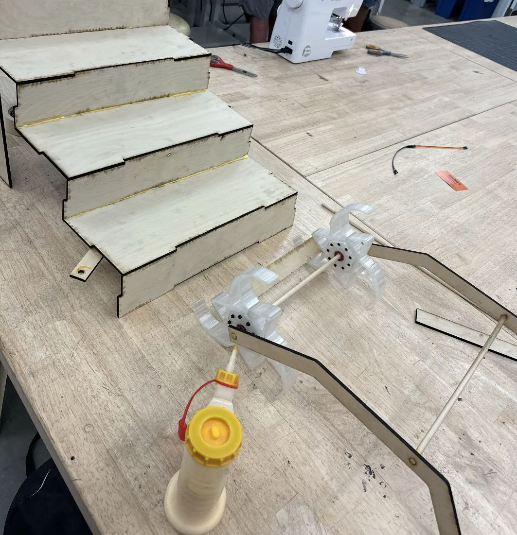
A working prototype wheel that rolls on bearings, with a full set of drawings, fits, and manufacturing plans for both the prototype and production scale.
Engineering detail
The full story for anyone who wants to dig in: design decisions, numbers, and what didn't work.
The idea
Roughly four million older adults in the U.S. use walkers, and stairs are one of the hardest things for them. Our concept replaces the walker's wheel with a curved-spoke tri-wheel. As each spoke rolls over the edge of a step, the walker stays near level. The user only has to apply force forward, leaning slightly into the walker, so they don't need to lift it and reposition at every stair.
Compared with a single wheel, a tri-wheel can climb. Compared with other tri-wheel systems, ours is built to handle steps of different heights.
How the wheel is built
Each wheel has two hubs and six spokes, with three spokes bolted to each hub using M3 socket-head bolts and nuts. Bearings press into the center of each hub and ride on a dowel that acts as the axle. Spacers keep the wheel off the wooden handle, and wooden supports glued between the two wheels make them turn together.
| Part | Qty | Prototype process |
|---|---|---|
| Wheel hub | 2 | FDM 3D printing (Creality Ender 3) |
| Wheel spoke | 6 | FDM 3D printing |
| Bearing | 4 | Press-fit into the hubs |
| Bolt and nut | 18 each | Standard M3 hardware |
| Handle | 2 | Laser cut wood |
| Wheel support | 3 | Laser cut wood, glued between wheels |
| Dowel (axle) | 2 | Cut to length with a handsaw |
| Spacer | 2 | Clearance fit over the dowel |
Choosing the manufacturing process
For every component I compared the realistic ways to make it and wrote down the trade-offs. For the printed wheel, FDM 3D printing won because it made rapid iteration possible and handled the complicated spoke geometry, even though printed parts are weaker and need support removal. CNC milling would give tighter tolerances and tougher material but wastes stock and is slower on small features.
For the handles and wheel supports, the laser cutter was fast and precise for simple extruded shapes, with charring along the cut as the main drawback. A CNC router would repeat better for production runs but is slower for one-offs.
I did the same exercise for production scale. In production, the wheel spokes and hubs would be CNC milled from aluminum, bolts and nuts cold-formed, handles lathe-turned, and the frame joined by welding.
Tolerances and fits
A wheel on bearings only works if every joint has the right fit: bearings that stay put, axles that don't slide, bolts that go through freely, and spacers that let the axle spin. I specified each fit from ANSI grades and recorded whether the process chosen for each part could actually hold it.
| Joint | ANSI fit | What the fit has to do |
|---|---|---|
| Bearing in hub | LN1 | Hold the bearing firmly in the hub |
| Dowel in bearing | LN2 | Keep the dowel from sliding axially in the bearing |
| Dowel in handle | LN2 | Fix the axle in the handle, no axial or radial play |
| M3 bolt in spoke and hub | RC4 | Let the bolt pass through freely and align the spokes |
| Bolt head in counterbore | RC8 | Let the bolt sit flush inside the hub |
| Spacer on dowel | RC2 | Hold a fixed gap while the dowel spins freely |
LN is a locational interference fit; RC is a running or sliding clearance fit.
This also showed where our process was the limit. The table flags that the 3D printer can't hold the tight tolerances on the printed hub and spoke joints, while the lathed and laser-cut parts can.
What I learned
- Scope matters more than ambition. Cutting the project down to the wheel made everything else, including the manufacturing choices, simpler and better.
- Design for the process you'll use. Printing, laser cutting, and sawing each push the geometry and tolerances in different directions.
- Fits are a design decision. Choosing LN versus RC grades up front prevented trial and error at assembly.